Entrance length refers to the pathways or gates allowing players and officials to access the field, usually designed for smooth movement. Boundary thickness denotes the width of the boundary rope, typically 3-5 cm, ensuring visibility and safety. According to ICC standards, the rope must be at least 2.74 meters away from obstacles, providing a clear and safe play area.
In cricket, the entrance length and boundary thickness are often overlooked but important aspects of ground setup:
Entrance Length:
- Refers to the dimensions of pathways or gates leading players, officials, and ground staff onto the field.
- These entrances are typically wide enough (2-3 meters) to accommodate multiple players, equipment trolleys, and security personnel.
- The entrance length varies based on the stadium’s design but ensures smooth movement and quick access to the field.
Boundary Thickness:
- This refers to the width of the boundary rope or demarcation line that separates the field of play from the spectators or perimeter.
- According to ICC guidelines, the boundary rope must be a minimum of 2.74 meters (9 feet) away from any obstacle for player safety.
- The rope itself is usually about 3-5 centimeters thick, providing clear visibility for players, umpires, and spectators.
Both aspects are crucial for maintaining safety, accessibility, and clarity in the game.
Hydrodynamic Entrance Length
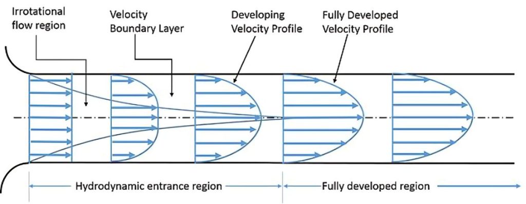
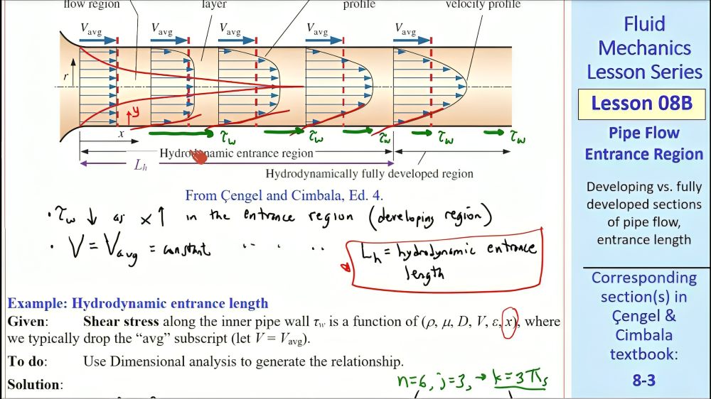
The hydrodynamic entrance region is the section of a pipe where fluid flow transitions from uniform velocity to a fully developed velocity profile due to viscous forces. When fluid enters a pipe, it initially flows uniformly. However, at the pipe’s surface, the no-slip condition causes the fluid in contact with the wall to stop. Viscous forces then slow down adjacent fluid layers near the surface, while the central layers accelerate to conserve mass. This interaction forms a velocity gradient across the pipe’s cross-section, characterizing the entrance length.
Boundary Layer
The boundary layer is the region within a flow where shearing viscous forces are significant. This layer is a conceptual division that separates the flow into two distinct regions:
- Boundary Layer Region:
A region where viscous effects and velocity changes are prominent. - Irrotational (Core) Flow Region:
Also called the inviscid core, this is the area where viscous effects and velocity changes are negligible.
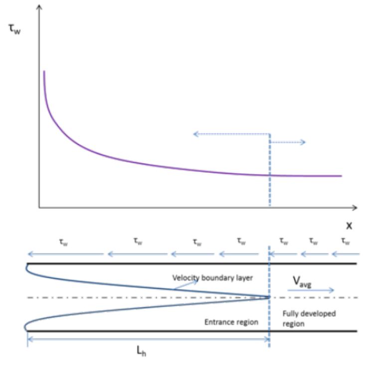
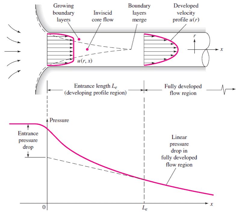
When fluid enters a pipe, the boundary layer starts forming at the entrance and gradually thickens as it moves along the flow direction. Eventually, it extends to the pipe’s center, filling the entire cross-section. The section from the pipe entrance to the point where the boundary layer fully develops is known as the hydrodynamic entrance region, and the corresponding length is called the hydrodynamic entry length.
In this region, the velocity profile evolves, resulting in hydrodynamically developing flow. Beyond this, the velocity profile becomes constant, marking the hydrodynamically fully developed region. However, for fully developed fluid flow, the normalized temperature profile must also stabilize and remain constant.
In laminar flow, the velocity profile in the fully developed region is parabolic. However, in turbulent flow, the profile becomes flatter due to intense radial mixing and eddy motion.
In the fully developed region, the velocity profile remains constant. For laminar flow, the hydrodynamic fully developed condition is mathematically expressed as:
This indicates that velocity depends only on the radial coordinate x
Calculating Hydrodynamic Entrance Length
The hydrodynamic entrance length is the length of the entry region in a pipe where the flow develops fully. It depends on the flow’s Reynolds number (Re).
For laminar flow, the entrance length is:

For turbulent flow, the entrance length is shorter:

In practical applications, this effect becomes negligible beyond a pipe length of approximately
10 times the diameter:

Entry Length for Pipes with Non-Circular Cross-Sections
For pipes with non-circular cross-sections, the entry length can be determined using the same formula as for circular pipes, with a slight modification. A parameter called the hydraulic diameter is introduced, relating non-circular pipe flow to circular pipe flow. This method is valid as long as the cross-sectional shape is not overly distorted.

Average Velocity of Fully Developed Flow
By applying a force balance on a small volume element in the fully developed flow region of a pipe (Laminar Flow), the velocity is found to depend only on the radius, meaning it is independent of the axial distance from the entry point. The velocity as a function of radius is derived as:

By definition of average velocity is given by:

where Ac

For fully developed flow, the maximum velocity will be at

Thus,
Thermal Entrance Length
The thermal entrance length is the distance required for the incoming flow in a pipe to develop a stable temperature profile. This profile depends on the heat flux and temperature conditions along the pipe’s inner wall, as well as the properties of the fluid.
Overview
An example is a pipe covered by an electrical heating pad, where the flow is introduced once the heat flux from the pad stabilizes. After traveling a certain distance from the entrance, the fluid reaches a fully developed heat flow state, where the heat transfer coefficient and temperature profile become constant. This distance is known as the thermal entrance length, a crucial parameter for engineers designing efficient heat transfer systems.
Laminar flow
For laminar flow, the thermal entrance length is a function of pipe diameter and the dimensionless
The thermal entrance length in fluid flow is influenced by the
- Reynolds number (ReD)
- Prandtl number (Pr)
The Prandtl number, a dimensionless quantity representing the ratio of momentum diffusivity to thermal diffusivity, modifies the hydrodynamic entrance length to determine the thermal entrance length.
For fluids with Pr>1Pr > 1, the thermal entrance length is longer than the hydrodynamic entrance length. Conversely, for Pr<1Pr < 1, it is shorter. For instance, molten sodium, with a low PrPr value of 0.004, has a much shorter thermal entrance length compared to its hydrodynamic entrance length.
For turbulent flows, thermal entrance length may be approximated solely based on pipe diameter.
where
- xfd,t
is the thermal entrance length and
- D
is the pipe inner diameter.
Heat Transfer in Fluid Flow
The temperature profile within a fluid flow is influenced by heat transfer conditions at the pipe’s inner surface. Heat transfer can occur due to either constant heat flux or constant surface temperature:
- Constant Heat Flux: Often caused by external heating sources like heat tape.
- Constant Surface Temperature: Commonly results from phase transitions, such as steam condensation on the pipe surface.
Newtons law of cooling describes convection, the main form of heat transport between the fluid and the pipe:
qs″=h(Ts−Tm)
where
- qs″
is the heat flux into the fluid,
- h
is the convection coefficient,
- Ts
is the surface temperature, and
- Tm
is the mean stream temperature.
Constant surface heat flux result in Ts−Tm

Thermally Fully Developed Flow
In contrast to hydrodynamically developed flow, thermally fully developed flow is characterized by a constant temperature profile shape, even as the temperature continues to approach the ambient temperature. Dimensionless analysis is used to quantify changes in the profile shape, determining the point at which the flow is considered thermally fully developed.
Requirement for thermally fully developed flow:
Thermally developed flow exhibits reduced heat transfer compared to developing flow due to a smaller temperature gradient. In thermally developed flow, the temperature difference between the pipe’s surface and the mean flow temperature is larger than the temperature difference near the pipe boundary.
Concentration Entrance Length
The concentration entrance length is the distance required for the concentration profile in a flow to become fully developed. It can be estimated by correlating it with the hydrodynamic entrance length using the Schmidt number, which represents the ratio of momentum diffusivity to mass diffusivity, or by experimental methods.
where
- xfd,c
is the concentration entrance length,
- D
is the pipe inner diameter,
- ReD
is the Reynolds number (based on the pipe diameter), and
- Sc
is the Schmidt number.
Applications of Entrance Length in Flow Systems
Understanding entrance length is crucial for designing and analyzing flow systems. In the entrance region, velocity, temperature, and other flow profiles differ from those in the fully developed flow region of a pipe.
Flow Meters
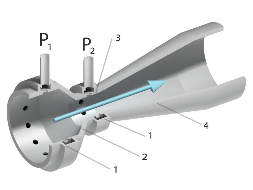
Many flow meters, such as vortex and differential-pressure flow meters, require hydrodynamically fully developed flow to function accurately. Achieving this often involves using long, straight pipe sections upstream of the flow meter. Alternatively, flow conditioners or straightening devices can be employed to create the necessary flow conditions. These measures ensure accurate readings and optimal performance of the instrumentation.
Wind Tunnels
Wind tunnels utilize smooth, inviscid airflow to study an object’s aerodynamics. Flow straighteners, made of parallel ducts, minimize turbulence and ensure a uniform flow. The entrance length is critical in wind tunnel design, as the object being tested must be placed in the irrotational flow region, located between the flow straighteners and the entrance length.
Exit Length
At a pipe’s exit, the velocity profile undergoes changes, similar to the flow development at the entrance. However, the exit length is significantly shorter than the entrance length and has minimal impact at moderate to high Reynolds numbers, making it less critical in most designs.
Hydraulic exit length for laminar flows may be approximated as:
where
- x
is the exit length,
- D
is the pipe inner diameter, and
- Re
is the Reynolds number.


